Relay Modules
CANopen I/O modules
Increasing complexity of control systems in machines and plants and a strong tendency to decentralization induced by an increasing use of intelligent subsystems explain the boosted communication needs between control and peripheral systems in todays machine and plant control. Ever-growing data amounts require a high-performance bus system which is able to transmit large bulks of data between intelligent control elements in a reliable and quick manner.
Input and output modules (I/O modules) are peripheral modules of a PLC in the bus system: Input modules collect information on the processes to be processed. Via the bus system data items are transmitted to the control unit where they are processed.

DOLD CANopen I / O modules:
- Potential-free relay outputs ensure troublefree operation
- One-stop offering: I/O modules fitting to DOLD CANopen PLC
- One-stop offering: DOLD’s complete range includes input and output modules
- Plug&Play mode: Save cost by sparing the sliprings for wireless transmission of multiple input and outputs
CANopen field bus system:
- Wide choice from compatible devices from different manufacturers
- Open standardized CANopen system offers independence of specific suppliers
- High extent of reliability and fault tolerance
- Fast transmission of small quantities of data
Field bus systems, general
- Easy and clear wiring
- High flexibility of systems with respect to changes and extensions
- Easy incorporation of control concepts in overriding management systems (gateway)
- Save up to 40% of cost for projecting, installation, commissioning and maintenance
Key data of the CANopen field bus system
- Bus topology: Line with short stubs
- Twisted pair line, shielded
- Typical line impedance: 120 Ω (equivalent to line termination). Note: Reflections on the line ends can be avoided by bus line termination on both ends with the bus line's characteristic impedance (120 Ω).
- Max. 32 nodes without repeater, with repeater up to 128 nodes
- Relation between baud rate and bus length: 5000 m at 50 kBaud; 10 m at 1000 kBaud
Line structure
The CANopen bus system is implemented as a line structure with bus terminations on both line ends. The use of shielded lines improves its electromagnetic immunity. Electromagnetic interferences can also be avoided by the use of optical fiber cables. However this variant is more expensive compared with shielded cables. Connection of optical fiber cables is via integrated or external opto-couplers.
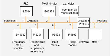
The figure below shows an example of how to use the DOLD CANopen PLC IL 5504 MINIMASTER for distributon boards as well as further bus nodes for the CANopen field bus system.

Bus connection
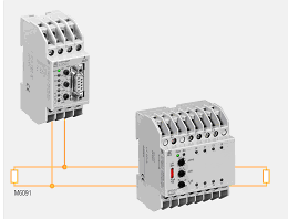
Bus nodes can be looped in the bus line or connected to the bus line via a short stub (max. 30 cm). To identify bus nodes an address (node ID) is assigned to each of them. The figure below shows the basic structure of a typical CANopen node connection to a bus with DOLD-PLC IL 5504 MINIMASTER and output module IP 5503:

- Mobile systems: Automotive, rail vehicles, ship building, special-purpose vehicles such as mobile machines for wood working
- Traditional machine controls
- Building system automation, e.g. market gardens
- Small power stations
CANopen I/O Modules | |||||
| Function | Number of inputs/ outputs |
Relay output |
Thermal current lth [A] |
Housing Style: Width [mm] |
Type |
|---|---|---|---|---|---|
| Input module, digital | 8 I | Distribution board: 70 | IP 5502 | ||
| Input module, analog | 2 I | Distribution board: 35 | IL 5508 | ||
| Output module, digital | 8 O | R | 2 | Distribution board: 70 | IP 5503 |
| Output module, analog | 2 O | Distribution board: 35 | IL5507 | ||
| I/O module, digital | 4 I, 4 O | R | 2 | Distribution board: 52.5 | IN 5509 |

